June 2006
Medical Center A
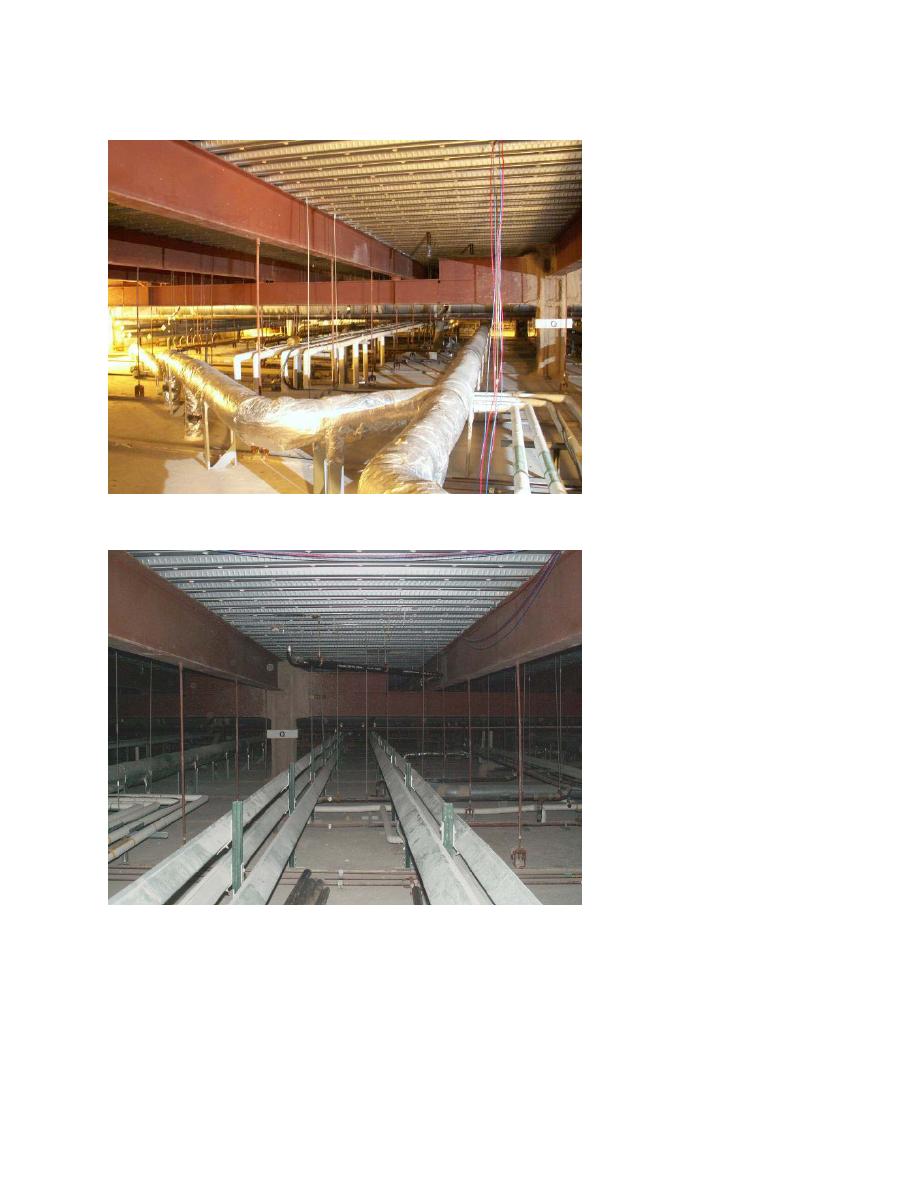
Note dropped girder in S-2
subzone.
Note non-compliant tele-
phone/data cabling.
Note branch ducts supported
from platform.
Photo A-5
Interstitial Service Zone
Showing typical distribution subzones and channels
S-2 subzone. Note dropped
girder in background.
S-4 subzone. Hanger rods
are visible at both sides of
channel for electrical wire-
ways.
Channel for HVAC is to left.
Note HVAC piping (insulated)
and plumbing are crossing at
right angles in S-5 subzone
below.
Photo A-6
Interstitial Service Zone
Showing Electrical channel in Subzone S-4
SUPPLEMENT TO RESEARCH STUDY REPORT
VA HOSPITAL BUILDING SYSTEM
APPENDIX A-11


 Previous Page
