(h) Air Distribution:
(1) The main supply air ductwork shall be sized to deliver the supply
air fan capacity, 612 Cu M/Min (21,840 CFM) as calculated in the
example above.
(2) The individual room air distribution system including supply,
return, exhaust air ductwork, air terminal units, reheat coils and air
outlets/inlets shall be sized and selected on the basis of the adjusted
supply air volume, 588 Cu M/Min (21,000 CFM).
(3) The fan and motor selection shall be based on the supply air fan
capacity and static pressure adjusted, as necessary, for the altitude,
temperature, fan inlet and discharge conditions, and the AMCA 201
System Effect Factors. The fan selection shall be made within a stable
range of operation at an optimum static efficiency. The fan motor W
(BHP), required at the operating point on the fan curves, shall be
increased by 10 percent for drive losses and field conditions to
determine the fan motor horsepower. The fan motor shall be selected
within the rated nameplate capacity and without relying upon NEMA
Standard Service Factor. See VA Standard Detail 15000-50 for the energy
efficient motors.
(g) Motor Voltages:
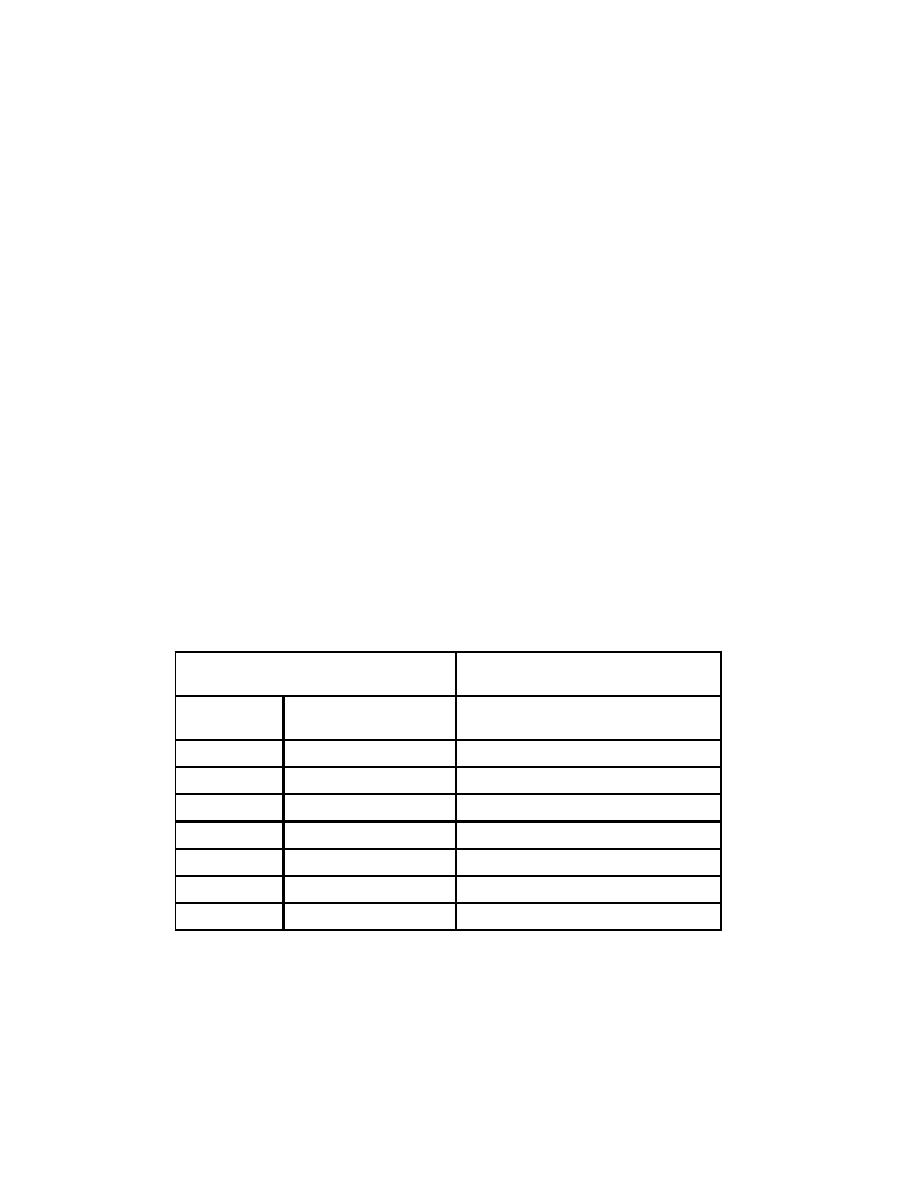
(1) Motor Voltages shall conform to NEMA/ANSI standard as follows:
Table 1-5 System/Motor Voltages
System Voltage (Transformers)
Utilization Voltage
(Motors)
Nominal
With 4 Percent
Standard (For Schedule)
Drop
120
115.2
115
208
199.7
200
240
230.4
230
480
460.8
460
600
576.0
575
2400
--
2300
4160
--
4000
1.3.15.2 CHILLED WATER SYSTEMS
(a) The capacity of the chilled water system, which consists of
condenser and chilled water pumps, cooling tower, piping, etc. shall be
based on the sum of the total cooling requirements of all connected air
handling units. See paragraph 1.3.15.1 for the derivation of the total
cooling load requirements for air handling units. No additional safety
factors should be required.
HVAC DESIGN MANUAL
1-17
GENERAL REQUIREMENTS


 Previous Page
