740
Example Service Module: Opening Configuration
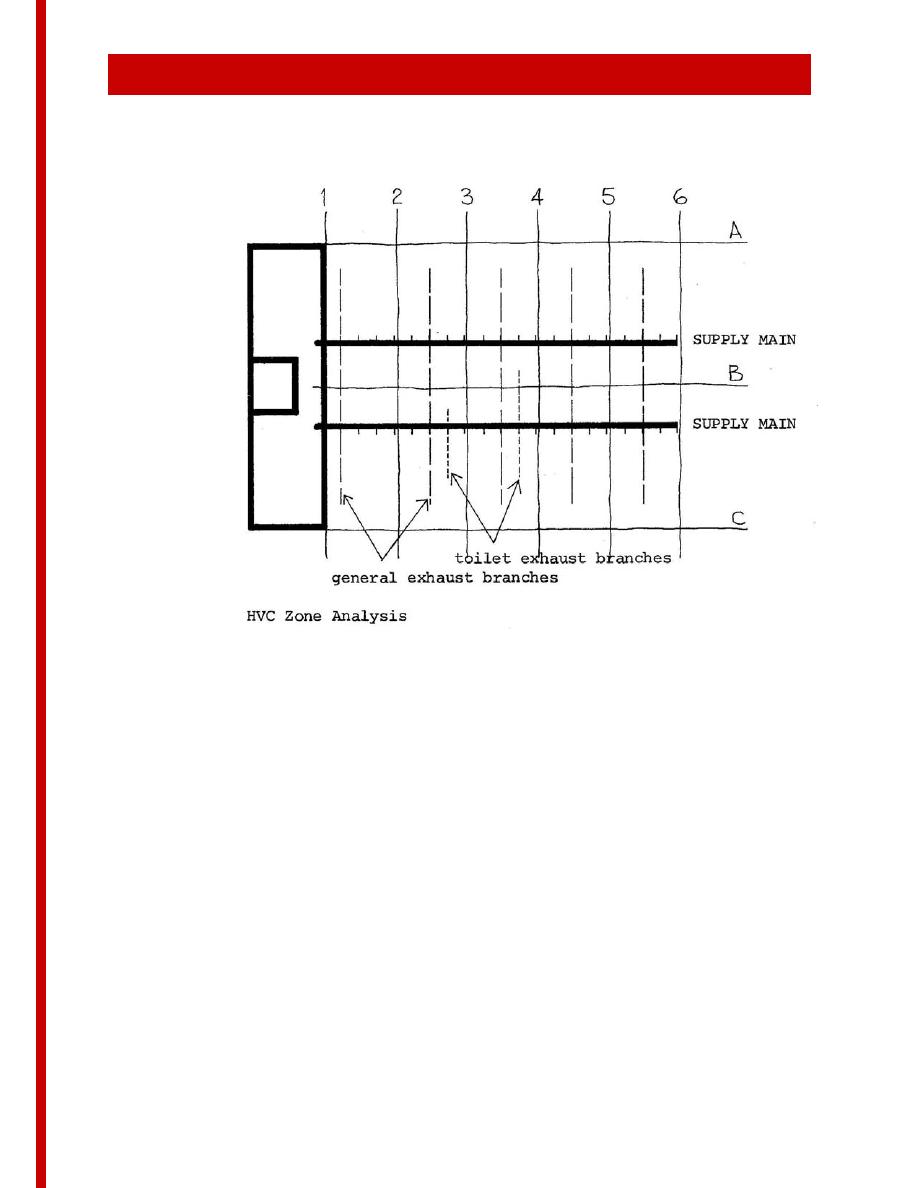
3. The number of possible branch supply duct locations in this service bay
is forty, based on two main supply ducts, five bays long, each with four
hanger spacings per bay (assuming one HVC branch per spacing); that
is, 2 x 5 x 4 = 40.
4. Each general exhaust branch would occupy two of these possible
locations per bay, and the two special exhaust branches one each, as
shown on the sketch; that is, (5 x 2) + 2 = 12.
5. The resulting 28 remaining locations were then organized to provide the
24 supply zones, with the use of flexible duct connections in the S5
subzone as required.
It is recognized that there may be areas of a hospital where several small
adjacent rooms requiring separate zoning would require a modification of
this pattern. In such cases, supply branch ducts could be taken from both
sides of the mains, or more than one branch per hanger space could be
allowed.
3 - 147


 Previous Page
