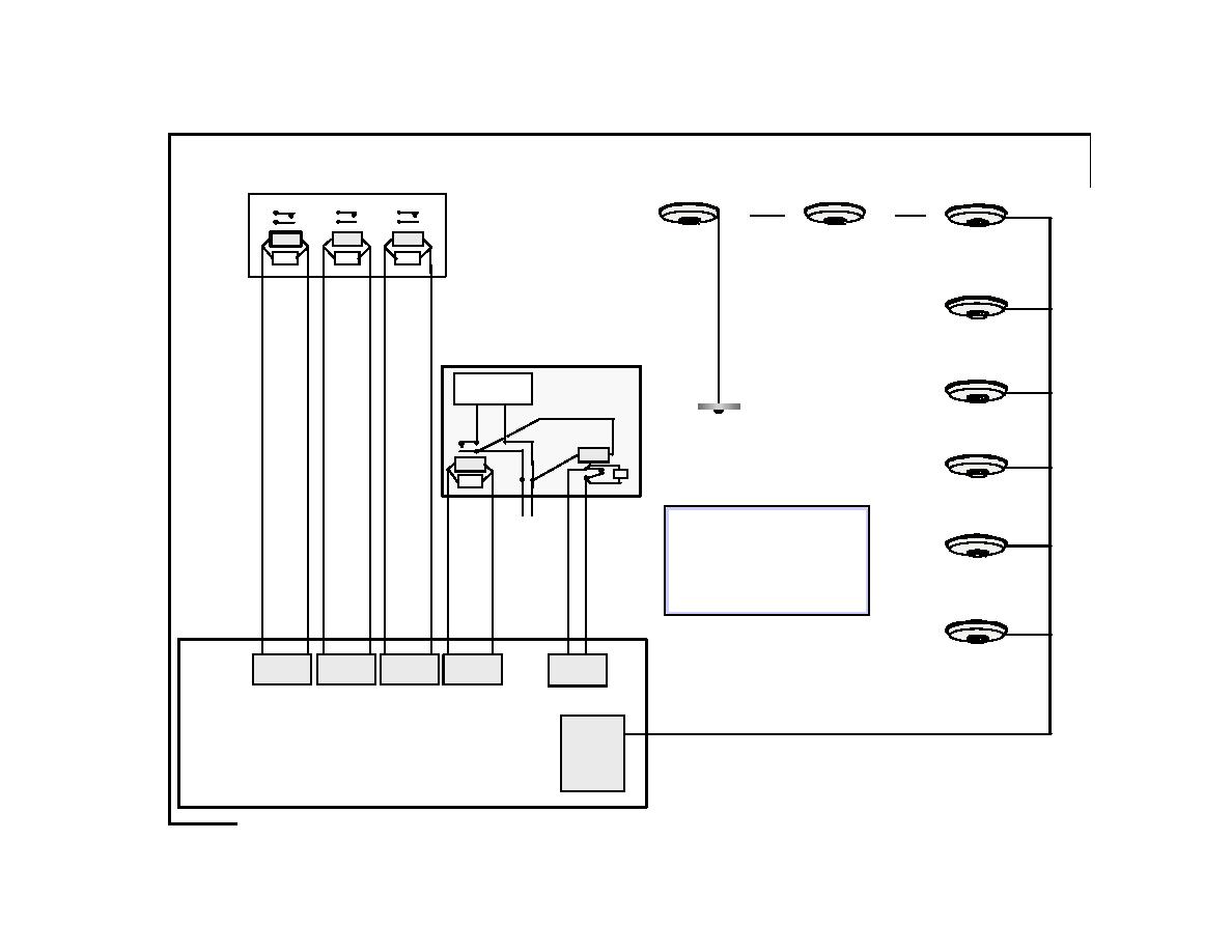
Pictorial Representation of Fire Alarm Interface with Elevators
Elevator Controller
Elevator
Elevator
Elevator Lobby
R1
R2
R3
Hoistway
Machine Room
Smoke Detector
Smoke Detector(s)
Smoke Detector(s)
5th Floor
EOL
EOL
EOL
Elevator Lobby
Smoke Detector
Elevator Power
4th Floor
Shunt Trip
Shunt Trip Breaker
Elevator Lobby
Elevator Hoistway &
Smoke Detector
Machine Room
3rd Floor
Heat Detectors
R5
*
R4
*relayR5contacts
EOL
Elevator Lobby
shownunenergized
EOL
2nd Floor
(Alternate Level)
Hot
Neut
Note:
120VAC
Only one Class"B" addressable circuit is shown
Circuit
for concept purposes. In reality, for survivability
(Power to Operate
reasons, addressable devices would be spread
the
among multiple addressable circuit modules, run
Shunt Trip Breaker)
Elevator Lobby
in Class "A" configuration, and/or be split up by
Ground Floor
circuit isolators.
(Designated Level)
Refer to accompanying page which provides
explanation and details of intended operation.
Elevator Lobby
Smoke Detector
IDC 1
Basement
NAC 4
NAC 1
NAC 2
NAC 3
(Supervisory)
Addressable
Circuit Module
Fire Alarm Control Panel
Bruce Fraser - 7/29/97
FA - Elevator Interface.ppt
- 30 -


 Previous Page
